
This form is not needed for nodes that do have relationships, since the specification of the relationship implicitly identifies the nodes as well.ĭuplicate entries are ignored.
CYTOSCAPE SAVE NETWORK LAYOUT HOW TO
The third line indicates how to specify a node that has no relationships with other nodes. This second form is simply shorthand for specifying multiple relationships of the same type with the same source node. The second line also specifies three relationships, all of type typeB and with node2 as the source, with node3, node4, and node5 as the targets. The second line specifies three new nodes, node3, node4, and node5 here "node2" refers to the same node as in the first line. The first line identifies two nodes, called node1 and node2, and a single relationship between node1 and node2 of type typeA. Lines in the SIF file specify a source node, a relationship type (or edge type), and one or more target nodes: The main disadvantage is that this format does not include any layout information, forcing Cytoscape to re-compute a new layout of the network each time it is loaded. It also makes it easy to combine different interaction sets into a larger network, or add new interactions to an existing data set. The simple interaction format is convenient for building a graph from a list of interactions. All file types listed (except Excel) are text files and you can edit and view them in a regular text editor. Once the interactions have been loaded and network layout has been performed, the network may be saved to GML or XGMML format for interaction with other systems. Typically, SIF files are used to import interactions when building a network for the first time, since they are easy to create in a text editor or spreadsheet. The SIF format specifies nodes and interactions only, while other formats store additional information about network layout and allow network data exchange with a variety of other network programs and data sources.

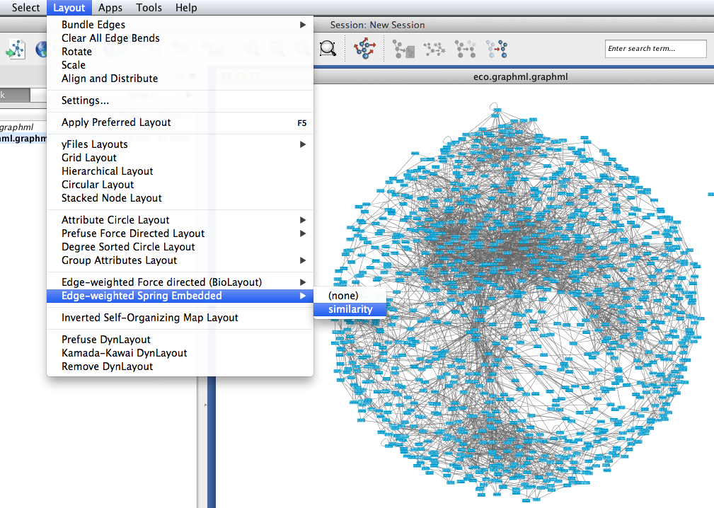
The circular algorithm produces layouts that emphasize group and tree structures within a network. The layout algorithm sets the positions of the nodes in a way that minimizes the sum of forces in the network. These springs repel or attract their end points according to a force function. The connections between nodes are treated like metal springs attached to the pair of nodes. Network nodes are treated like physical objects that repel each other, such as electrons. Similarly to Prefuse Force Directed, the Edge-weighted spring-embedded layout is also based on a “force-directed” paradigm as implemented by Kamada and Kawai (1988). Checking the Selected Only checkbox will restrict the actions to selected nodes. These tools include a set of tools for scaling, aligning, distributing, stacking and rotating the network and nodes.
CYTOSCAPE SAVE NETWORK LAYOUT MANUAL
For manual manipulation of the network layout, a set of Node Layout Tools are available in the Layout Tools tab of the Control Panel or via Layout → Node Layout Tools.


 0 kommentar(er)
